Function Block Diagram (FBD) PLC Programming Tutorial for Beginners
One of the official and widely used PLC programming languages is the Function Block Diagram (FBD). It is a simple and graphical way to program any functions together in a PLC program. Function Block Diagram is easy to learn and provides a lot of possibilities.
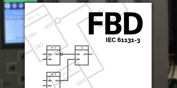
FBD is a key PLC programming language, officially recognized in the IEC 61131-3 standard. It’s versatile, letting you smoothly integrate logic, timers, PID controllers, and even SCADA system into your projects.
Most engineers love FBD because it is graphically a very common way to describe a system. Engineers like to put things in boxes. And that is exactly what the concept of function block diagrams is. FBD is very useful when batch control concepts from ISA-88 are applied.
In this tutorial I will introduce you to some of the basic principles of FBD programming and the function blocks.
Content of FBD Tutorial
What is Function Block Diagram?
Function Blocks in FBD
Standard Function Blocks
Bit Logic Function Blocks
Bistable Function Blocks
Edge Detection
Timer Function Blocks
Counter Function Blocks
Comparison Function Blocks
Selection Function Blocks
Make your own Function Blocks
What is Function Block Diagram?
From systems engineering you might already know something also called function block diagrams. PLC function block diagram is not that different from it. What FBD offers is a way to put functions written with many lines of code into boxes.
Thereby we can easily connect them, to make a bigger PLC program.
FBD, just like ladder logic and structured text, follows the IEC 61131-3 standard from PLCOpen. It’s common in PLC programming, often used alongside structured text, as it provides a straightforward way to connect various functions within your program.
Function Blocks
In FBD all functions are put into function blocks. They all have one or more inputs and outputs. The function of the block is the relation between the state of its inputs and outputs.
Here’s how a simple function block could look like:
Function block illustration in FBD
The function block is illustrated with a box. In the middle of the box is often a symbol or a text. This symbol represents the actual functionality of the function block.
Depending on the function there can be any number of inputs and outputs on the function block. You can connect the output of one function block to the input of another. Thereby creating a Function Block Diagram.
Combining function blocks to make a basic function block diagram
FBD offers many predefined function blocks, but you also have the flexibility to create your own. This is particularly useful when you need to reuse code, like controlling a motor or valve. Custom function blocks let you tailor your program efficiently, using the same block multiple times.
Let’s begin by having a look at some of the standard function blocks as described in the IEC standard for PLC programming languages. They provide a variety of functions from very basic to advanced.
Standard Function Blocks
In the standard from IEC, a lot of function blocks are described. Here’s an overview of the most important blocks in the official FBD description.
Bit Logic Function Blocks
The most basic functionality of a PLC […]