PLC Ladder Logic Programming Tutorial (Basics)
One of the best visual programming languages is a PLC programming language called ladder logic or ladder diagram (LD).
The great thing about ladder logic is that it’s much more visual than most programming languages, so people often find it a lot easier to learn.
What’s cool about ladder logic is its resemblance to electrical relay circuits. This means if you’re somewhat familiar with relay control and electrical circuits, you’ll likely pick up ladder logic more swiftly.
But that’s definitely not a requirement, and I myself didn’t understand relays when I first learned ladder logic.
In this ladder logic tutorial, you will learn everything you need to know about the ladder diagram PLC programming language. You will be able to start making real PLC programs with ladder logic in almost any PLC programming software.
After reading this tutorial I strongly recommend that you continue with part 2 of the course. If you want to deepen your understanding further, you can also take an online PLC programming courses.
Let’s get started!
GO TO PART 2 OF LADDER LOGIC TUTORIAL ->
Ladder Logic PLC Programming Tutorial
What is Ladder Logic?
Introduction to Ladder Logic
Relay Ladder Logic
Ladder Logic Basics
Ladder Logic Programming with Instructions
Examine if Closed
Output Coil
Output Latch
Examine if Open
Building Logic with Ladder
What is Ladder Logic?
Ladder logic (also known as ladder diagram or LD) is a programming language used to program a PLC (Programmable Logic Controller). It is a graphical PLC programming language which expresses logic operations with symbolic notation. Ladder logic is made out of rungs of logic, forming what looks like a ladder – hence the name ‘Ladder Logic’.
Ladder logic is mainly for bit logic operations, although it is possible to scale a PLC analog input. Even simple bit logic operations can be beneficial in more advanced PLC programs and SCADA system programming.
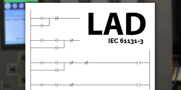
The group setting the ladder logic standards is PLCOpen. It’s more than just a PLC programming language; it’s a standardized one, following the IEC 61131-3 standard. The key takeaway? Ladder logic follows a globally recognized standard, making it universally consistent.
Introduction to Ladder Logic
To get you started with ladder logic there are a few things you should know about the programming language. You should know why ladder logic was invented because then it will be much easier for you to understand it. Especially if you have prior experience with electrical circuits and relays or some boolean logic.
Invented for Technicians
Ladder logic is a graphical programming language which means that instead of text, the programming is done by combining different graphic elements. These graphic elements are called symbols.
One of the smart things about the ladder logic symbols is that they are made to look like electrical symbols. Ladder logic was originally created for technicians, electricians, and people with an electrical background. People who are used to look at electrical diagrams and schematics.
Take a look at the symbols and see if you think they look familiar.
Just as in electrical diagrams ladder logic have symbols for contacts and relays (which are called coils in ladder logic). The symbols may look a little different from the ones you […]