All About PLC Analog Input and Output Signals and Programming
Do you know how to scale your analog input? Or wire your analog output?
Many people struggle with analog signals in PLC programming. The wiring and how to use an analog input or output in your PLC program can be tricky. Most often you will see digital example PLC programs and in my Structured Text Tutorial most of the examples are digital programs.
I’m writing this article because many of you wanted to learn how to use analog signals in PLC programming. Analog signals are used widely in PLC programs but also often used in a SCADA system. So how do you connect that 4-20mA analog transmitter to your PLC and use it in your PLC program? How do you scale an analog signal in Function Block Diagram? This article will give you answers to this and much more.
In this article you will learn about:
Analog Signals in the PLC
Representing Analog Signals with Binary Numbers
Bits and Bytes
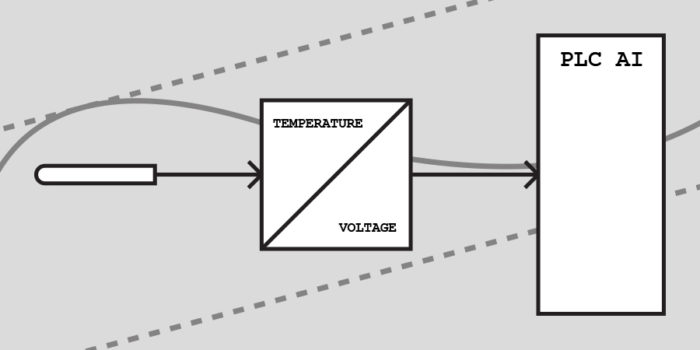
A/D Converter
Resolution of Analog Signals
Analog Signal Range
Analog Inputs
Wiring of PLC Analog Inputs
Voltage Analog Inputs
Current Analog Inputs
2-wire Analog Input
3-wire Analog Input
4-wire Analog Input
Analog Input Scaling
Analog Outputs
Wiring of PLC Analog Outputs
Voltage Analog Outputs
Current Analog Outputs
Analog Output Scaling / Unscaling
But first, let me start out with some basics about analog signals and how they work in a PLC.
Analog Signals in the PLC
First of all, we are going to look at some numbers. If you’ve read my article about combinatorial logic you will know that a PLC works with boolean values. A PLC can only work with the values 0 and 1.
This is great for digital signals. They are either 0 or 1 and thereby relatively easy to work with. But what about analog signals? As Wikipedia writes, analog signals are continuous signals that can vary over time.
For example you can have a 0-10 volt analog signal. This signal can vary from 0 to 10 volts and have any voltage level in between. And since analog signals are continuous, this signal will always at any time represent a voltage level. If you look at the diagram below, you will see that the analog signal can have any value between 0 and 10 volts.
0-10 Volt Analog Signal
The question is now: how do a PLC deal with all these different values? Let’s say you have an analog signal at 5 volts going into the PLC. We cannot represent it with boolean values, because they can only have the values 0 and 1.
The answer is binary numbers!
Representing Analog Signals with Binary Numbers
As mentioned before a PLC can only work with the two values 0 and 1. But that does stop us from working with analog signals. Because what is really going on, is that the PLC works with binary numbers. This is due to the fact that a PLC or a microcontroller is really just advanced electrical circuits made out of transistors. Since a transistor can only be either on or off, these two states will then represent the values 0 and 1.
But this only gives us two states. Very useful for […]